What parts?
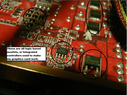
Those parts. Each part in an induction heater does something very important, and all induction heaters involve some type of semiconductor device to make it work. I will try my best to throughly explain all types of semiconductors used in induction heaters below.
The Vacuum Tube
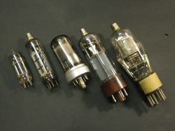
The Vacuum tube. These babies are the electronics of yesterday, and are still even being used today in alot of applications due to their simple robustness. They are very very hard to kill, and thankfully because tubes are rather expensive. A vacuum tube is a type of thermionic (okay so sue me, its not really a semiconductor) amplifying device used in a wide variety of things. They are mainly amplifiers, and were used for radio's and televisions way back before transistors were invented. A vacuum tube consists of several parts, the anode (plate), filament (cathode), and the grid. High voltage, somewhere around 600 volts, however this voltage can vary widely for different tubes, is applied to the anode part of the tube. Then, the control, or the signal voltage is applied to the grid part of the vacuum tube, which changes the amount of current and voltage that flows from the anode to cathode, essentially creating a variable resistance, allowing for amplification and switching. The filament is the part of the tube that heats up, allowing for the thermionic emission of electronics. Vacuum tubes in induction heating are usually very large, as they need to be able to withstand high currents and high voltage for periods of time. The JFET is the type of semiconductor that is the most related to this device in terms of operation.
The Bipolar Junction Transistor (BJT)
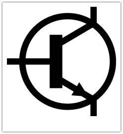
We begin at the base of the transistor.
BOOM. A signal is applied to the base, and turns on or off the transistor. The transistor suddenly starts screaming, as the current tickles the transistors arm. It starts to let go of the current at the collector. The current then flows from collector to emitter, at a certain amount based off of something called gain.
An NPN transistor may have 100 gain. This would cause, well, let's put it into a scenario. You have 10 mA of current pushing at the NPN transistor's base. The transistor "lets go" of 1 amp of current at the collector, and lets 1 amp flow through it. This amount of current, times the voltage drop will give you a rough estimate of how much heat your NPN transistor will generate, and whether or not you'll need to heat sink it. NPN transistors are used for controlling positive currents.
Common NPN transistors
2N3055
2N3904
TIP31
2N2222
PNP transistors work in a very similar way to NPN transistors, but instead of positive voltage, it uses negative voltage. If we took a 2n3906, a common PNP transistor, and applied 10 mA of current to the base, about 1 A of current will be allowed to flow through the collector and emitter, just negative voltage instead of positive voltage.
PNP transistors, other than that change, are essentially exactly alike NPN transistors, in that they are used in amplifiers, radios, computers, everything electronic.
Common PNP transistors
2N3906
2N6054
2N4403
MOSFETS! (Metal Oxide Screen Field Effect Transistor)
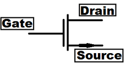
The MOSFET can be compared to the transistor as a much more effective switching device. There are three pins, just like transistors, and they are called the Drain, Gate, and the Source (ooo fancy).
The Drain and Source can be compared to the collector and emitter of a transistor, respectively. The gate is exactly like the base, except a MOSFET is a voltage controlled device.
Well, this means that instead of applying current you apply voltage. A MOSFET is a very ON or OFF device.Mosfets are much more suited to switching than being used linearly, but they CAN be used linearly. The heat created by a mosfet in it's linear stage (inbetween on and off) is about the same as a transistor. The only reason that mosfet's aren't suited for this is the voltage level threshold for mosfets is different for each device. That can not be said for BJ transistors. A transistor is best used for amplifying signals, and a mosfet is best used for switching. Before, transistors did both jobs, and frankly they sucked at switching.
MOSFETS, like transistors, have voltage drops, saturation, and something new, ON state resistance. This is basically how much the mosfet resists, as it is saturated or turned fully on. MOSFETS have increasing on resistance as voltage handling ability increases.
Basically, try to think of the MOSFET as a variable voltage controlled resistor. More voltage = more on, but this can only be turned on more to a certain point, until you start damaging the FET. Most MOSFETS have a limit to how much voltage can be put onto the gate, usually it's around +- 20 volts, but some can handle +-30 volts. Exceed this, and you will decrease your mosfet's life on this earth. The on state resistance does allow you to calculate how much heat your mosfet will generate by allowing you to use Ohm's law. (W = I2 * Ron) There are two more unique properties to mosfets, and those two are the intricate body diodes, and the turn off and turn off time. The body diode is inherently formed when a MOSFET is birthed, due to the alternating P- N channels of doped silicon. You cannot remove this diode, it is created as soon as the mosfet is created. If this diode is too slow for high frequency applications, you may need to bypass the diode and add your own ultrafast one.
Now, Turn off and turn ON times are extremely important, when working with frequencies over 5 kHZ or so. Turn on time is basically the amount of time it takes for the MOSFET to turn on, once the gate has received a signal. MOSFETS, when compared to their newer cousin, the IGBT, (to be explained in a bit) are a LOT faster, and have turn on times of anywhere from 20 nS (nanoseconds!) or 20 billionths of a second to turn on, to, any time in the world. It depends on which MOSFET you are referring to. Turn off times, and delay's are often a little bit longer than turn on times. Turn off times and delays can range from 30 nS to 1000 nS. If you turn on/off the mosfet faster than it can, it generates heat, and a LOT of it, plus your circuit will/may fail to work properly. Mosfets also have something called Input capacitance. The way a Mosfet is made basically creates a dielectric within the mosfet. The input capacitance varies, but for the most part it is around 2200 pF to 10000 pF. This complicates driving mosfets, and is the exact reason gate drive anythings exist. The more current that is available allows the input capacitance to be charged up faster. This may not sound like that big of a deal, especially with the little capacitance there is, but at high frequencies, this causes mosfets to turn on and off more slowly, inducing heating and problems. Ringing on the gates is also a massive problem, as mosfets have capacitance, and there is inductance on the leads. This basically creates an LCR circuit, and can damage/kill your mosfet if it's bad enough. Gate resistors help prevent this, along with snubbers. (usually involve resistors and capacitors, and sometimes zener diodes). MOSFETS that have more current handling ability generally have more capacitance than ones that have lower current ability. This generally has to do with how big the die size is. Bigger die = more capacitance for you + more current.
Mosfets ALSO have an important factor to note; avalanching. This is the same avalanching I was talking about with TVS diodes. MOSFETS can avalanche voltage across them as excess heat. This makes these types of mosfets perfect for fly-back transformer purposes, as voltage spikes can kill a mosfet that isn't avalanche rated. Not all are avalanche rated; the datasheet will tell you if they are or not. Moving on, there are roughly two types of mosfets, P channel, and N channel, the N channel mosfet being the more common one out of the two.
MOSFETS are used in many many digital devices, due to their simple nature as on off devices. (think binary, what is it?)
Because they are used for switching, they can be used as relays, light blinkers, sound generators (like synthesizers), Switch mode power supplies, CPU logic, gate logic, oscillators, like your laptop's backlight, if it still uses CFL's that is.
MOSFETS are used in a quite a few hobbyist's circuits as well.
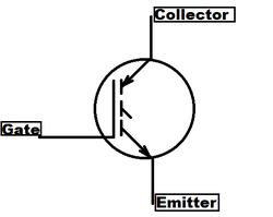
IGBT (Insulated Gate Bipolar Transistor
Now, you may be thinking, "Oh Jared, its just a transistor with a fancy name!" WRONG.
An insulated gate bipolar transistor, is the equivalent of taking a mosfet, and regular bipolar transistor, and shoving them together. They made babies!
And boy, do these babies pack a punch.
IGBT's are voltage controlled devices, just like MOSFET's. They combine the high current capability and the low saturation voltage (complete on) of a transistor, and the simple gate drive of a mosfet. They have three pins, just like every other device. The pins are labeled Gate, Collector, and emitter. The collector is the equivalent of the drain of a mosfet, and the emitter, the source of a mosfet.
Basically, they're pretty snazzy. But, we don't live in a perfect world.
IGBT's have their fair share of issues as well. They have a positive temperature coefficient, like transistors. Meaning, the more hot it gets, the more current it conducts, causing thermal runaway and a dead IGBT (this happens in a split second for the most part).
Compared to MOSFET's, IGBT's are somewhat slower in their turn off and turn on times. They can usually handle anything from 0 hz to around 40-50 khz, for the most part, though faster IGBT's do exist. It really depends on the actual device itself.
IGBT's are renowned for their current handling ability. Most can handle upwards of 50 amps, and more, at voltages above 600 volts! They are perfect for low frequency, high current, high voltage purposes, where mosfets are good for High frequency, lower current, and lower voltage purposes. But, like mosfets, they also have input capacitance, and ringing issues. Take the same measures you would with a mosfet to prevent this, using resistors and a clean signal source. Shorter leads also help.
IGBT's do NOT have intricate body diodes, like mosfets do. However, manufactures often do you a favor, and put a high speed high voltage diode in with the IGBT package, for ease of use. Be sure to check how fast the diode is when using the IGBT with high frequencies. But, there are exceptions, some IGBT's don't have diodes in them at all, and may require you to add one outside of the package. You need to put the anode of the diode (pick an ultrafast high amp 1000-1200 volt diode) to the emitter of the IGBT. This will allow voltages to freewheel if needed, preventing your IGBT from blowing up.
IGBT's are used in welders, induction heaters (I love these), microwave ovens, and in quite a few applications where MOSFETS have also been used. I have yet to see an IGBT amplifier, though.
There is only one type of IGBT. No N channels or P channels!
Diodes
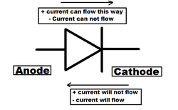
Diodes are perhaps one of the more common components, and were among the first to be invented actually. A diode is a type of doped p - n device that prevents current from flowing in one direction, allowing for alot of interesting things to be done.
A diode can be used to rectify alternating current, which will be explained in a later step,
A diode can be used to create a radio, because of the above property, it can demodulate the carrier signal and output a pulsing DC wave, which is the sound you could hear. Most radios nowadays take advantage of more complicated silicon, increasing the part count dramatically but also increasing loudness and ease of use, along with better sound quality of course.
Diodes are quite inexpensive, compared to other semiconductor devices, because it's relatively easy to manufacture compared to other doped silicon, as well as because of mass production and demand.
There are TONS, and I mean TONS of different diodes, but they all perform (nearly, there is an exception) the same thing as every other diode.
Diodes to exhibit some odd characteristics, mainly one being the voltage dropped across it. Most standard diodes have a voltage drop of from .4 volts to .7 volts. Certain diodes have even lower voltage drops, some Schottky diodes have voltage drops of only .2 volts! This voltage drop is important, because it allows you to determine how much heat a diode will create, based off of how many amps you plan on putting through it, and if you need to heatsink it or not. Most diodes are pre rated for you, however.
Capacitors
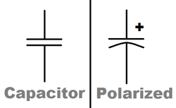
Capacitors are extremely simple. After all, they're just two plates of metal, separated by something insulating. The more surface area there is, the larger the capacitance. Most non-electrolytic capacitors are under 30 uF, though there are exceptions.
Different capacitors are made quite differently. An electrolytic, for example, takes advantage of the extremely high surface area of aluminum oxide. (the plates are constructed from aluminum foil, basically, and an electrolyte is added to change the aluminum into a really nice oxide coating).
Other than that, most capacitors are *relatively* the same. The main difference between them is the insulating material between the plates. Polypropylene, polyester, paper, oil, mica, ceramic..... Polypropylene capacitors are the best kind for induction heating. They typically are rated EXTREMELY well, with great current handling ability and voltage ratings. Polyester ones are NOT suitable at all. They do not like being pushed hard, and will overheat/die.
Paper and oil capacitors will not work either. Mica capacitors, however, will work FANTASTIC. The only issue being is that they are extremely expensive, since it's hard to find mica that is of high quality to make the capacitor! But, if you can somehow find a capacitor large enough for induction heating, use it. Mica caps have a very low ESR. (effective series resistance, basically means how much resistance the capacitor has in a circuit)
With ceramic capacitors, it depends. Little disc ones won't work. However, there are larger ones MADE specifically for induction heating that will work great!
Typically, with any capacitor, the larger the size physically, the more current it can handle.
